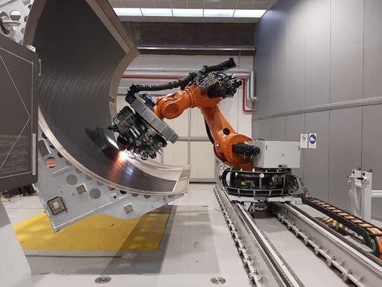
End-of-arm tooling (EOAT) is the part of a robot cell that is designed last and blamed first. The robot is chosen, the cell is laid out, and then the gripper or tool plate has to fit within the remaining payload. When the tooling gets heavy, teams often end up slowing the robot down or buying a larger one. Carbon fiber is one way out of that corner. This post explains why tooling weight matters, where carbon fiber helps, and what to plan for when designing composite EOAT.
Is your end-of-arm tooling eating your payload?
Talk with CMI’s engineers about a lighter composite design.
Why Tooling Weight Matters
A robot’s payload rating is not only for the part being moved. Yaskawa defines payload as “the amount of weight including the tool the robot can handle on the wrist axis” (Yaskawa Motoman). So the gripper itself counts against the rating.
Static weight is only part of the story. The same guide advises engineers to “closely examine the allowable load moment and inertia at the wrist,” and to align the payload’s center of gravity with the robot’s axes of rotation (Control.com). Yaskawa, for example, notes that beyond the payload rating there are additional moment and inertia requirements, and that these values “must not be exceeded” (Yaskawa Motoman). Mass that sits far from the wrist, such as long tool arms or wide vacuum frames, quickly uses up those limits.
Speed and precision are affected too. Researchers designing a robotic gripper note that inertia forces from high-speed arm movement “make the system harder to stop on precise points,” and that grippers need to be compact or use lighter materials to reduce these effects (Păduraru et al., Machines).
Where Carbon Fiber Helps
Carbon fiber composites are valued for their high stiffness-to-weight ratio, a point a 2025 materials review makes about drone structures (Vietnam et al., Journal of Composites Science). Long, cantilevered tooling needs the same combination. Gripper suppliers are already making the case. FFT, a German automation company, has introduced a carbon fiber profile system for robotic grippers as an alternative to aluminum profiles, reporting weight savings of up to 41% compared with aluminum and saying the lower moving mass increases achievable dynamics without needing a higher-payload robot (CompositesWorld). Those are the manufacturer’s figures for its own product, but they show the size of the opportunity.
Composite EOAT tends to make the most sense when:
- The tool is large or reaches far from the wrist, such as panel, sheet, or multi-pick grippers
- The cell is limited by cycle time and the robot is running near its payload or inertia limits
- The alternative is upgrading to a larger robot
- The tool must stay stiff so parts are placed accurately at speed
It may not be worth it for small, compact grippers near the wrist, where the weight saved is small compared with the cost of tooling and engineering.
What to Plan For in Composite EOAT Design
Interfaces and hardware
The EOAT must bolt to a tool changer or wrist flange and carry cylinders, vacuum cups, sensors, and cable routing. Those attachment points are where composite designs succeed or fail. Metal inserts can be molded into the composite so hardware fastens securely, a process CMI covers on its co-molding carbon fiber with metal page.
Stiffness, not just strength
Tooling that bends or vibrates at the end of a fast move costs settling time and placement accuracy. The laminate should be designed for stiffness in the directions the tool is loaded, which is where finite element analysis earns its keep. For more on vibration, see our post on how carbon fiber affects system resonance.
Impact and fatigue
Robot tooling is loaded and unloaded every cycle and occasionally bumps into things. Composite parts handle repeated loads and impacts differently than metal, and some impact damage is hard to see. Read more on our page about how carbon fiber behaves under impact and load cycling.
Information to bring
- Robot model, payload rating, and published wrist moment and inertia limits
- Workpiece weight, size, and center of gravity
- Tool changer or flange interface
- Hardware to mount: cups, cylinders, sensors, and cable routing
- Target cycle time and placement accuracy
- Expected quantity of tools
How CMI Supports Robotics and Automation Programs
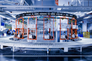
Robotics is one of the industries CMI serves. CMI’s engineering team uses CAD/CAM, finite element analysis (FEA), and 3D-printed and CNC prototypes to develop composite parts, and builds its molds in-house. Production processes include prepreg layup, resin transfer molding, vacuum infusion, and compression molding, with 3-, 4-, and 5-axis CNC trimming. Because CMI machines both composites and metals and can co-mold metal inserts, the composite structure and its metal interfaces can come from one shop. Learn more about CMI’s custom composite engineering, or read our earlier post on how composite materials support faster industrial machine speeds.
Get more out of the robot you already have.
Send CMI your tooling concept and payload limits for an engineering review.